
CEE
PURLINS
- G500
G450
- <1.5mm - 500
>1.5mm - 450
- Z 275
- Fastbrace
Bolted Brace Channel
Overview
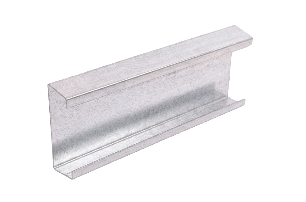
The Dimond Structural CEE Purlin range is available in 22 sizes from CEE 100/10 to CEE 400/30 to suit commercial applications up to 18m spans. Purlins are intended for use as structural support to profile metal roofing and wall cladding. CEE Purlins are manufactured in Auckland.
Material Specification
Dimond Structural Cee Purlins are manufactured by roll forming galvanised steel coil produced to AS 1397.
BMT - Base Metal Thickness
Z450 zinc weight coil can be supplied with order lead times of up 12 weeks. Contact Dimond Structural on 0800 DIMOND (0800 346 663)
Tolerances
Length:
- CEE Purlins ± 6mm
- Bracing System ± 2mm
Depth/Width:
- CEE Purlins ± 2mm
- Bracing System ± 1mm
Holes Centres: ± 1.5mm
Web/Flange Angle: 89-93 degrees
Specific Design
Design Basis
Dimond Structural CEE Purlin Systems have been designed to comply with AS/NZS 4600:1996, based on physical testing and analysis carried out by the University of Sydney, who are recognised for their expertise in the area of cold form design. The structural analysis consisted of several modules including cross-sectional analysis, an AS/NZS 4600:1996 design module, inplane structural analysis, and finite element lateral buckling analysis.
Methods in AS/NZS 4600:1996 for determining pure shear, combined bending/shear, lateral buckling and distortional buckling have, in some cases, resulted in lower purlin capacities than previously published. These are included in the design tables in the Purlin Systems Manual.
Appropriate design load combinations for each Limit State should be determined in accordance with AS/NZS 1170. It is recommended these be expressed as uniformly distributed bending loads (kN/m) assumed to be acting in-plane applied about the major axis of symmetry (X-X) and uniform axial compression loads (kN) applied about the rotational axis (Z-Z) for direct comparison with the tabulated data in this manual.
Self weight of the CEE Purlin Systems is not included in any load tables and must be calculated as part of the total dead load of the building elements supported by the purlin.
CEE Purlin System Design Considerations
Data presented in the Purlin Systems Manual is intended for use by structural engineers. Load situations other than uniformly distributed and axial loads will require specific design.
Design capacity of the CEE Purlin System is largely dependent on the amount of restraint provided to the purlin section. Data presented in CEE Purlin System Load Span Tables 1.3.4 assumes that bracing prevents both lateral movement and rotation of the section at that point.
Design Capacities in the Limit State format have been derived by the application of a capacity factor, Φ:
Bending Φb = 0.90
Compression Φc = 0.85
A design yield strength of 500 MPa has been used for CEE purlins and girts. This is in line with the minimum specified yield for G500 material and is less than the consistent minimum yield stress in the G450 material used in manufacture.
Tables in the Purlin Systems Manual are intended for use where roofing or cladding is attached to one CEE purlin or girt flange, where it is assumed that the screw-fastened cladding significantly prevents lateral movement of the flange to which it is attached. Where this assumption does not hold, it is recommended that the number of braces required is specified such that the purlin load capacity, ΦbWbx is not less than the capacity for the Fully Restrained (FR) case.
Gravity type loads can be assumed to act perpendicular to the roof plane for roof pitches up to 10 degrees provided the DHS purlins are placed with their flanges facing up the slope. For roof pitches greater than 10 degrees, load components about the minor axis of symmetry (Y-Y) should also be considered.
Span Guide
As a guide, single spans are used most frequently, particularly where purlins/girts are set down between the rafters/columns.
Deflections may govern on larger spans.
End and internal continuous configurations may be used where lower deflections are required.
Lapped end and lapped internal configurations are more economical on large purlin spans where better strength and lower deflections are required.
Deflection Guidelines
As a guide to acceptable deflection limits for serviceability of the DHS Purlin System used as purlins or girts, the following limits are recommended for wind load and dead load actions,
- Where there is no ceiling:
- Deflection for Ws ≯ Span/150
- Deflection for G ≯ Span/300
- Where there is a ceiling:
- Deflection for Ws ≯ Span/200
- Deflection for G ≯ Span/360.
For further guidance on deflection limits, refer to AS/NZS 1170.
Bracing Guidelines
For roofs, the out of plane component of the dead load of the roofing and purlins is assumed to be carried in tension by Fastbrace or Bolted Brace Channels tied across the ridge or into the ridge beam for monoslope roofs. In order to minimise lateral deflections to purlin members, we recommend a maximum spacing between bracing lines and/or support framing of 3.5 metres.
For walls, the following table gives the maximum allowable wall heights for Dimond Structural bracing systems, where the dead load of cladding and girts is assumed to be carried in tension to an eaves beam by Fastbrace or Bolted Brace Channels.
In order to minimise deflections in the girt member, we recommend a maximum spacing between bracing lines and/or support framing of 3.5 metres.
Specific design of the bracing system and connections is required for wall heights greater than the limits shown or where the bracing is designed to carry compression loads.
BMT - Base Metal Thickness
Basis to table: 1) Maximum spacing of bracing lines/portal frames 3.5m and 2) Maximum cladding weight 6.7kg/m2
Specific Design
Specific design to AS/NZS 4600 is required where CEE purlins -
- have suspended loads present (such as ducting and piping). Suspended loads are connected to the CEE purlin web or, if this is not possible, to the CEE purlin bottom flange within 25mm of the web. Under no circumstances should loads be hung off the purlin lips.
- are used as cantilever members.
- are used as truss or portal members.
- have holes larger than standard bolt holes present.
- are subject to out of plane loading about the minor Y-Y axis.
For further specific design details refer to section 1.3 Specific Design - Purlin System in Purlin Design manual
Purlin Systems Durability
View Dimond Purlin Systems durability statement
Relevant Product CAD Details
Below you will find all of the relevant product CAD technical details in .dwg, & .pdf format.
If you have any questions regarding the details below please contact one of our technical team on 0800 550 660
Product Technical Statement
To help you get through the building consent process as quickly as possible, we have developed the Product Technical Statement (PTS) downloads to make it quick and easy for specifiers to access the documentation required.
The PTS downloads hold all of the information the council requires for a building consent where Dimond product is specified.
Product Brochure
Need a brochure for this product? Here you can download one with the basic information and details you need during the decision process.


